I make this amazing Electronics Project. It it a heart beat LED circuit.
Track: Warriyo – Mortals (feat. Laura Brehm) [NCS Release]
Music provided by NoCopyrightSounds.
Watch:

I make this amazing Electronics Project. It it a heart beat LED circuit.
Track: Warriyo – Mortals (feat. Laura Brehm) [NCS Release]
Music provided by NoCopyrightSounds.
Watch:

Electronics projects encompass a wide range of activities, from basic circuit assembly to advanced digital and analog applications. Beginners often start with simple tasks like creating LED circuits and using basic components like resistors, capacitors, and transistors to understand how electrical currents flow and how different components behave. Essential skills in reading circuit diagrams and using breadboards allow enthusiasts to quickly move from theory to practical application, making it possible to experiment with DIY projects and bring creative ideas to life.
As enthusiasts gain more confidence, they delve into more complex projects involving integrated circuits (ICs) such as 555 timers, operational amplifiers, and microcontrollers like Arduino. These components are the building blocks for creating interactive gadgets, such as timers, automated lights, and even basic robots. Circuit design software becomes crucial here, enabling the creation of custom PCBs to enhance project reliability and aesthetics. Projects can range from LED running lights that use digital logic ICs to manage timing sequences, to sophisticated home automation systems that integrate various sensors and networked communication.
For those interested in combining creativity with practical skills, LED projects offer a visually rewarding experience. From simple LED dimmer circuits to complex RGB LED control setups, these projects not only brighten up spaces but also teach important electronic concepts such as current limiting and pulse width modulation. As knowledge expands, hobbyists can tackle projects like designing their own schematic drawings and etching PCBs at home, furthering their understanding of electronics and circuit behavior. Whether it’s for educational purposes, professional development, or personal satisfaction, electronics projects provide a robust platform for innovation and learning.

How to Make Simple Volt Regulator | 0 to 50v 3A current #zaferyildiz #short #shorts #viral #led

How to Make Simple Volt Regulator | 0 to 50v 3A current
👉Get a free trial of Altium Designer with 365 and 25% off your purchase :
👉 👈
👉Learn about Altium 365, the electronics product design platform that unites PCB design, MCAD, data management, and teamwork: 👉
👉Free search engine for the best quality components from Octopart:
👉
👉 Circuit diagram & PCB
👉
👉 The soldering iron I use
👉
***Thank you for watching me. To help the video reach more people, please remember to like, comment, and share it. If you haven’t subscribed yet, you can support the channel by subscribing for free. Your feedback will help this video reach more people, and encourage me to find more resources to produce higher quality and new content for you Take care of yourself until we meet again in the next video and project. ****
#zaferyildiz
#regular
#viral
#electronics
#irfz44n

How to do touch Load Control / TT223 / No Relay
?Get a free trial of Altium Designer with 365 and 25% off your purchase :
? ?
?Learn about Altium 365, the electronics product design platform that unites PCB design, MCAD, data management, and teamwork: ?
?Free search engine for the best quality components from Octopart:
?
?Circuit Diagram – PCB – Layout Plan
pcb ?
?Circuit
Plan ?
? The soldering iron I use
?
? COMPONENT LIST
1X LM7805
1X RU6888 MOFET / IRFZ44N / IRF3205
1x Touch sensor TT223.
1x 100 Ohm
1x 10K
***Thank you for watching me. To help the video reach more people, please remember to like, comment, and share it. If you haven’t subscribed yet, you can support the channel by subscribing for free. Your feedback will help this video reach more people, and encourage me to find more resources to produce higher quality and new content for you Take care of yourself until we meet again in the next video and project. ****
#altium
#zaferyildiz
#Loadcontrol
#tt223
#toch
#circuit

Diodes Explained, in this tutorial we look at how diodes work, where diodes are used, why diodes are used, the different types. We look at diodes in half and full bridge rectifiers to convert AC to DC.
👓 Check this article:
Sign up for our FREE engineers newsletter for updates, competitions, news and offers
🎁 Link:
⚡🛠️ TOOLS YOU NEED 🛠️⚡
**************************************
Get this electronics book ➡️
Professional Multimeter -➡️
Good multimeter -➡️
Professional clamp meter ➡️
Good Clamp meter ➡️
Outlet tester ➡️-
Energy monitoring plug ➡️
Battery tester -➡️
Basic electronics kit ➡️
MY FAVOURITE GEAR
🎥 My camera –
🎤 My Microphone –
⌨️ My Keyboard –
🖥️ My monitor –
🎧 My headphones –
📺
Capacitors Explained: 👉
Voltage Explained: 👉
Current Explained: 👉
Electricity Explained: 👉
Power Factor Explained: 👉
👋 SOCIALISE WITH US 👋
*******************************
👉FACEBOOK:
👉TWITTER:
👉INSTAGRAM:
👉WEBSITE: Http://TheEngineeringMindset.com
👀 Links – MUST WATCH!! 👀
*******************************
⚡ELECTRICAL ENGINEERING⚡
👉How electricity works:
👉Three Phase Electricity:
👉How Inverters work:
👉How TRANSFORMER works:
👉How 3 Phase electricity works:
👉How Induction motor works:
👉What is a KWH:
👉How induction motor works:
❄️ CHILLER ENGINEERING ❄️
👉Chiller Efficiency improvements:
👉Chilled water schematics:
👉Chiller crash course:
👉Chiller types:
👉Chillers/AHU/RTU:
👉Water cooled chiller Part1:
👉Water cooled chiller Part2:
👉Water cooled chiller advanced:
👉Air cooled chiller:
👉Absorption Chiller :
👉Chiller COP calculation:
👉Chiller cooling capacity calcs:
👉Chiller compressors:
👉Chiller expansion valve:
👉Chiller surge:
👉Chiller condenser:
👉Chiller evaporator:
👉Chiller compressor centrifugal:
👉Chiller cooling capacity:
🌡️ HVAC ENGINEERING 🌡️
👉HVAC Basics:
👉Boilers/AHU/FCU:
👉How Heat Pump works:
👉Heat pumps advanced:
👉Fan Coil Units:
👉VAV Systems:
👉CAV Systems:
👉VRF Units:
👉Fan and motor calculations:
👉HVAC Cooling coils:
👉Cooling towers:
⚗️ REFRIGERATION SYSTEMS 🌡️
👉How refrigerants work:
👉Thermal expansion valves:
👉Refrigeration design software:
👉Design refrigeration system:
👉Reversing valve:
👉How A/C units work:
⚗️ REFRIGERANTS ⚗️
👉Refrierant retrofit guide:
👉Refrigerant types, future:
👉How refrigerants work:
🌊 HYDRONICS 🌊
👉Primary & Secondary system:
👉Pumps:
👉Pump calculations:
🔥➡️❄️ HEAT EXCHANGERS 🔥➡️❄️
👉Plate Heat Exchangers:
👉Micro plate heat exchanger:
💻 DATA CENTERS 💻
👉Data Center cooling:
🔬 PHYSICS 🔬
👉What is Density:
🎬 DOCUMENTARY 🎬
👉WW2 Bunker HVAC engineering:
pn junction, pn junction diode, semiconductores half wave rectifier semiconductor physics
#electrical #electricity #engineering

Come see how I made this Walnut & Brass Coat Rack!
Check out to learn more and save up to $100 when you start your next project.
TOOLS & SUPPLIES (affiliate links):
Long ago, before I put my projects on YouTube, I made a $10 Coat Rack from some simple Anna White plans, unfortunately that coat rack didn’t survive the move to our new house. But recently, I was at a West Elm store a while back and I saw a coat rack with some simple metal tips. I then realized that I could use a combination of my wood lathe and my new metal lathe to make a beautiful walnut coat rack with some classy brass tips.
I began this project by milling up some walnut into small rectangular pieces that will eventually become the hanger pegs. A few longer pieces were cut down and glued together to form 2-inch square stock about 6 feet long, this will become the center post. After cutting a test piece of pine, I decided that the center trunk should be a clean octagonal post with the pegs sticking out from the flat sides. The original piece of walnut I had was about 12 inches wide, so I cut off a 12 inch long section that would become the coat rack’s base. I bought some solid brass rod that needed to be cut down with the metal-cutting bandsaw.
My woodturning skills are slowly improving, so this project was going to push them to the limits. Each skinny rectangular piece had to be turned down to about 3/4 of an inch on the wood lathe. I used the square roughing tool to get a (semi)uniform thickness across the piece. This process took a while and made a huge mess, but it was really good practice turning rough pieces into straight cylinders. I then drilled some 1/2 inch holes into one end of each peg to accept the brass tips.
This was my first project using the metal lathe and boy was it a learning experience. I have watched many videos and know the concept, but that is no substitute for getting your hands on the machine and making some cuts. There were a few mishaps, I jammed up the machine at one point by pushing the cutter head too far into the brass stock, but after my heart stopped racing I adjusted and get back to work. I made a surfacing cut to clean up the face, and then slowly shaved down the cylinder to match the thickness of the walnut pegs. The tips were then flipped around in the chuck and I turned the tenon that would sit inside the holes on the end of the wooden pegs. Overall, I made 10 of these tips, some beautiful successes and some that were…not so beautiful, but overall a huge victory for me on the metal lathe!
Remember that big 12×12 inch piece of walnut I cut earlier? This gorgeous piece will become the coat rack’s base. I drew a large circle on the walnut face and then used the jigsaw to cut off the excess. Using the center point of that circle, I attached the screw chuck to the face and mounted it to the wood lathe. I thought a simple circle with a nice round over would look really nice and wouldn’t be too much fuss, so I carved that up really quick. To securely mount the tall center post to the base, I decided to cut an octagonal mortice into the base. Later on, I fit the center post snuggly into the base with some glue and just to be sure, I drove a screw up through the bottom to firmly attach the two.
I needed a uniform way to drill into the trunk so that the walnut and brass pegs can fit into it at a consistent angle. I couldn’t get that kind of accuracy drilling by hand, and using the drill press by itself could also be problematic. Josh made a quick jig that would attach to the drill press table and would hold the trunk firmly in place. We adjusted the drill press table to 45 degrees and clamped the piece into the new jig. This method worked perfectly and we got perfectly uniform 3/4 inch holes drilled at the proper spacing on each face. All we had to do was glue the pegs into the holes. I used some blue painter’s tape to cover the area around the holes to minimize any mess from the glue squeeze out. Once the pegs were dry, I finished the whole piece with a few coats of spray lacquer to protect it against constant use.
I encourage you to get out of your comfort zone and try something new. If you liked this project, check out more of my work
Subscribe:
Check out my TopVideos!:
Learn 3d modeling, get digital plans, and cool merch at
Want to support ILTMS? Get exclusive content and more…
FOLLOW:
#ILikeToMakeStuff
How to Make a Brass and Walnut Coat Rack // Woodworking & Metalworking | I Like To Make Stuff
I Like To Make Stuff

A television you can turn on and off using a remote controller! Remember to leave a like if you enjoyed! 🙂
Thank you to my patrons:
EmeraldMelon, Captain_Komodo, HwGroup, Sean Yang, PemapolMC, ClownsDontBite, AyyUltra, Sean Boniface, InfectaDoEmulators, Andreamine, Domo Trno, Olivia Redfern, NauPanda, Luke Brumley, Diamond Nuggets!
Patreon:
Translate this video:
Translate my channel:
Merchandize:
How to support a video:
Step by step tutorial:
Page link:
Facebook:
I use Fraps for recording and Camtasia for editing! 🙂
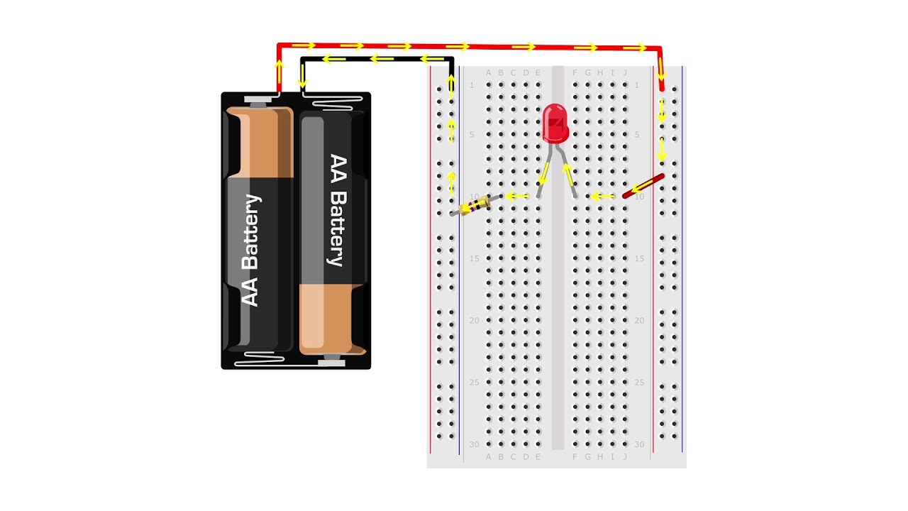
This tutorial shows you how to use a solderless breadboard to build an electronic circuit, including the basics of how a breadboard works and some common mistakes that beginners make. You can find the written tutorial at Science Buddies:
0:00 intro
0:35 why is it called a breadboard?
0:49 types of breadboards
1:14 how does a breadboard work?
1:57 what’s inside a breadboard?
2:40 breadboard rows and columns
3:08 power buses (rails)
3:56 which holes are connected?
5:00 simple circuit with LED
6:32 common mistakes
6:50 wrong row
7:20 loose wires
8:03 polarity
8:43 jumper wires
10:17 solid vs stranded wire
11:00 integrated circuits (ICs) and dual in-line packages (DIPs)
If you liked this video, you may also find our multimeter tutorial useful:
Are you wondering whether the resistor needs to be before the LED in the circuit? That’s the most common question we get about this tutorial! Check out this video for an explanation of why it’s OK to have the resistor after the LED:
Do you want to build the example circuit shown in this video? All the circuit parts you need are available on Amazon.com:
– Solderless breadboard:
– LEDs:
– 47 ohm resistor*:
– Jumper wire kit:
– 2xAA battery holder:
– AA batteries
* if you plan to do a lot of electronics projects, a resistor kit with more resistor values is a good investment:
Disclaimer: Science Buddies participates in an affiliate program with Amazon.com. Proceeds from the affiliate programs help support Science Buddies, a 501(c)(3) public charity, and keep our resources free for everyone.
Science Buddies also hosts a library of instructions for over 1,000 hands-on science projects, lesson plans, and fun activities for K-12 parents, students, and teachers! Visit us at to learn more.
#circuits #electronics #breadboard #STEM #sciencebuddies
*******************************
Connect with Science Buddies:
TWITTER:
FACEBOOK:
INSTAGRAM: